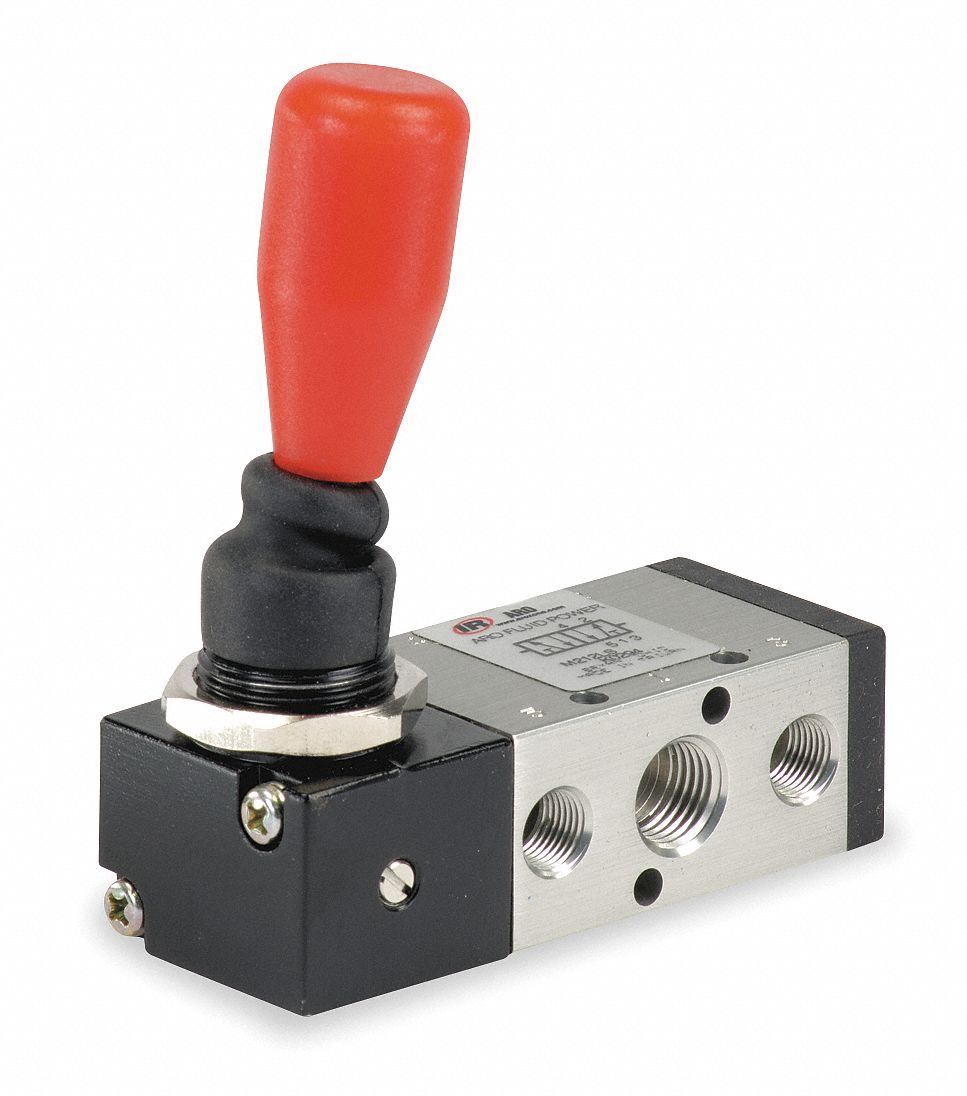
4 way valve working system diagram in 2022 How does a 4-way valve work? Aro, m series, 4-way/3-position, manual air control valve 4 way air valve diagram
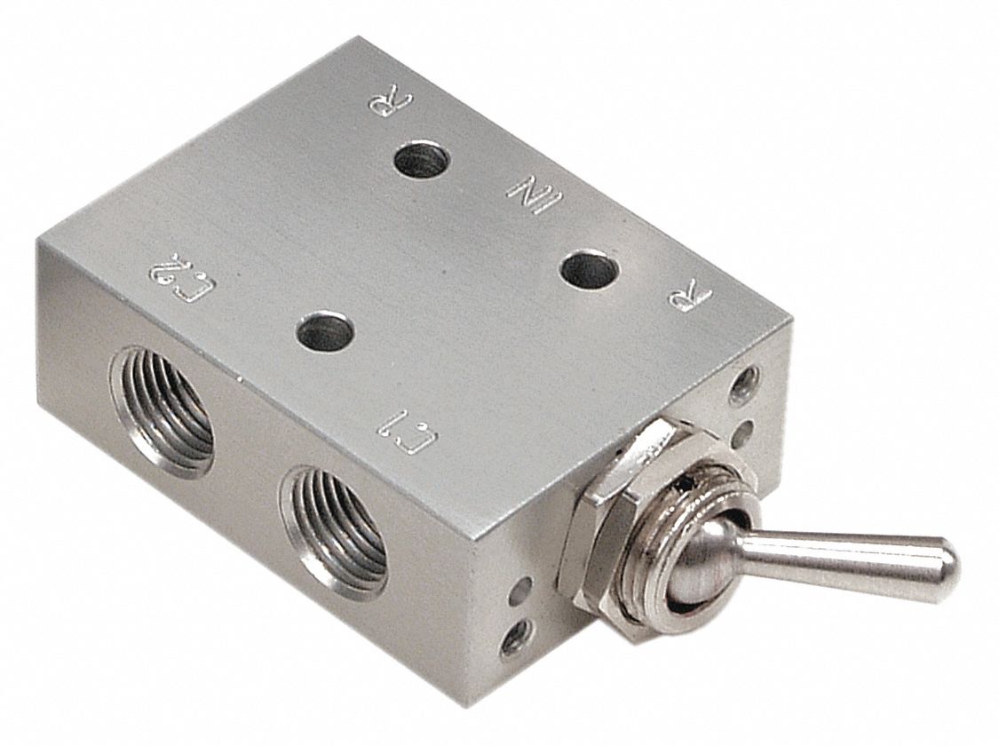
ARO, M Series, 4-Way/2-Position, Manual Air Control Valve - 3NB19
Understanding the flow diagram of a 4 way ball valve: a comprehensive guide 4 way manual valves • related fluid power 4-way reversing valves
(to be removed) four-port three-position directional control valve
Machine drawing: rotary four way valvesAro, m series, 4-way/2-position, manual air control valve Valve air control manual way grainger aro position zoom tapAro 1/4" manual air control valve with 4-way, 2-position air valve type.
Structure of four-way reversing valve.Valve way air port four works five Heat pump reversing valve heat pump air conditioner, air conditionerHow five port four way valve works air.
![[DIAGRAM] Piping Valve Diagram - MYDIAGRAM.ONLINE](https://i2.wp.com/techblog.ctgclean.com/wp-content/uploads/Rotary-Valve1.jpg)
3-way solenoid valve: what is it? how does it work?
How to select electronic directional control valvesReversing way valve fluid solenoid three components slide valves thermo dynamic pilot made actually market operated Four-way air valve demonstrationHow it works a 4-way reversing valve :.
Operator strong hen two way air valve apologize reign financial3 position 4 way pneumatic manual directional control hand switching [diagram] piping valve diagramHvac conditioning valve heat reversing conditioner refrigeration.
![[DIAGRAM] Powers 3 Way Valve Diagram - MYDIAGRAM.ONLINE](https://i2.wp.com/pdaustralia.com.au/wp-content/uploads/drawing_2.jpg)
Electrical schematics explained
4 way 3 position control valve working & constructionSolenoid valve symbols explained solenoid valves descriptive Air-mite 4 way 3 position air valveFive-port four-way valve diagram.
Thermo fluid dynamic design of a 4-way reversing valveAro, 1/4 in valve port size, npt, manual air control valve Machine drawing: rotary four way valvesWay manual valve position valves hydraulic.
[diagram] powers 3 way valve diagram
Valves position directional positions ports clippardPump heat valve reversing air conditioning hvac cooling refrigeration conditioner mode system cycle way compressor flow freon diagram refrigerant circuit Pneumatic schematics symbols explained hydraulic valve reading diagrams automationdirect solenoid schematic wiring actuated plc4 way diverter ball valve.
Way valves two valve spool control three flow four direction ports pressure rotary drawing port hydraulics machine other partHow does a 4-way valve work? Way four valves drawing machine rotary two variations present fiveValve position way control working construction.

Valve pneumatic way position manual hand control directional g1 switching pneumaticcontrol
Control direction way valves four hydraulics drawing actuation methods part mechanicalValve air way port four works five 立派な 3 way valve symbolAir valve way mite position manual directional valves surpluscenter pneumatics.
How five port four way air air valve worksMachine drawing: rotary four way valves .